

Zahid R. Shah ( Department of Radiology, Cuyahoga County, Hospital and Case Western Reserve University School of Medicine, Cleveland, Ohio. )
Richard E. Klimo ( Department of Radiology, Cuyahoga County, Hospital and Case Western Reserve University School of Medicine, Cleveland, Ohio. )
Kunjan Pillai ( Department of Radiology, Cuyahoga County, Hospital and Case Western Reserve University School of Medicine, Cleveland, Ohio. )
Errol M. Bellon ( Department of Radiology, Cuyahoga County, Hospital and Case Western Reserve University School of Medicine, Cleveland, Ohio. )
Zahid R. Shah ( Department of Radiology Cuyahoga County Hospital 3395 Scranton Road Cleveland, Ohio 44109. )
January 1984, Volume 34, Issue 1
Original Article

Absiract
The chest stand we have designed has produced consistently good results. Radiation exposure measurements are well below ICRP recommendations (Annals of ICPR, 1977) (JPMA 34: 17, 1984).
Introduction
Pediatric chest stands are used to immobilize infants and children during radiography of the chest and abdomen. Most designs currently available present cradles of various sizes, suspended in front of the cassette by a hook attached to the stand. Our chest stand is designed to enable the radiologic technologist to hold the child during radiography while at the same time providing adequate protection for the technologist. Radiation exposure to the technologist is well below ICRP recommendations.
Chest Stand Design and Function Deszgn
The chest stand we have designed consists of two vertical panels, child support and cassette holder, all mounted on a cart with 2” diameter wheels (Fig. ).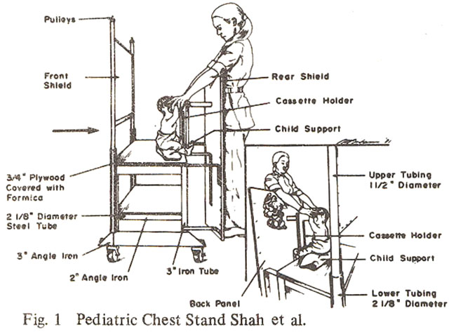
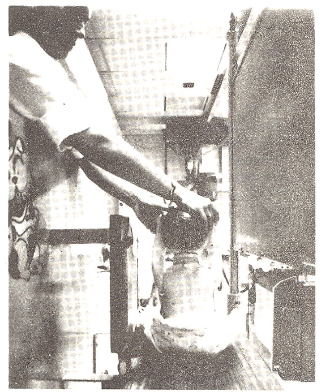
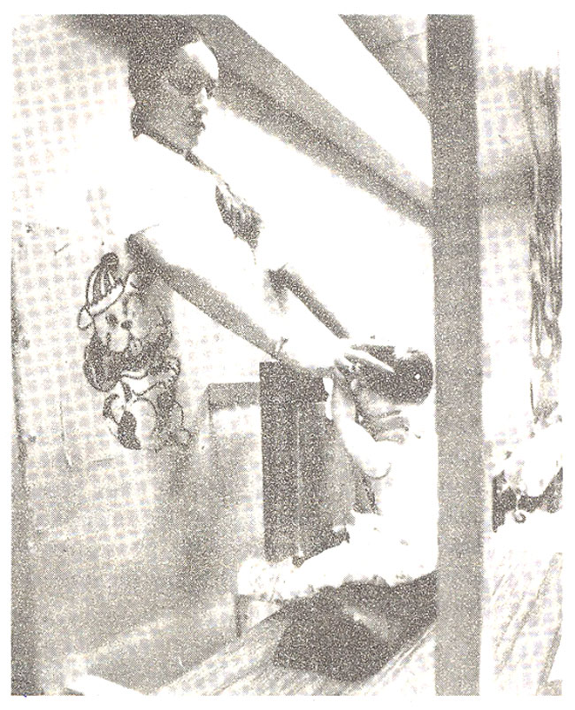
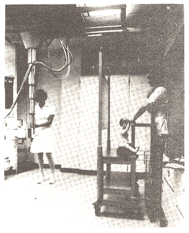
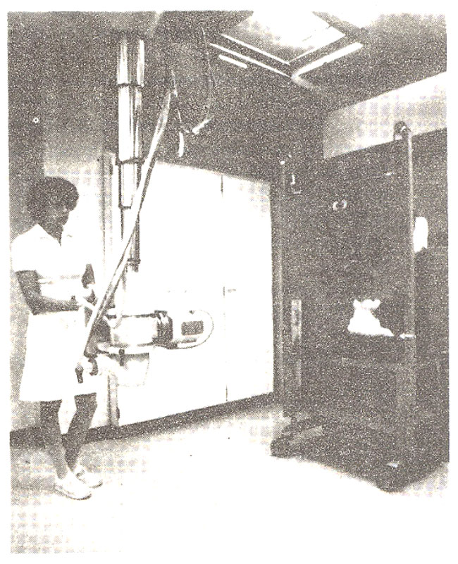
The front panel (the panel facing towards the x-ray tube) as well as the back panel (the panel in front of the technologist) consist of a sandwich of 1/8” plywood - 1/16” lead 1/8” plywood. The front panel (tube-side panel) is 33” long and 27” wide.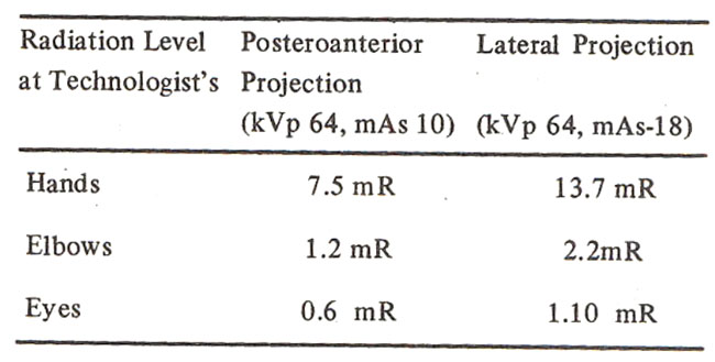
This panel is adjustable in height with the range of adjustment of the lower edge varying from 36-48” above the floor. This adjustthent is brought about with the aid of pulleys mounted on the top of the side ends of the front panel. Lead counterweights are housed in the front legs of the unit (approximately 10 lbs. in each leg). The pulleys are 2-3/4” in diameter and the distance between the pulleys and the lead weight is 42”. The second panel, that is the panel behind the child support and in front of the technologist, is 36” wide and 53” long and is fixed and not adjustable. The lower edge is 1” above floor level. The distance between the front and back panels is 22”. The film holder is mounted on the cart between the front and the back panels, at a distance of 6-1/2” from the back panel. The child support is a platform located between the film holder and the back panel.
The child rests on the child supports. The technologist stands behInd the back panel and holds the child with the forearms overhead, thus keeping the child’s arms out of the way of primary radiation. Sandbags may be placed on the child support for additional height in very small infants. Ideally, operation requires two technologists, one for adjusting the height of the front panel and for aligning the x-ray tube, while the other holds the child on the child support.. The front panel is lowered until its lower edge coincides with the upper edge of the collimated light beam. The lower edge of the front panel, when adjusted properly, is well below the level of the technologist’s hands.
Exposure is initiated by a foot switch or by the second technologist at the control panel. In either case the second technologist is not present in the room during exposure.
Radiation Exposure Measurements
Measurements were made to determine (1) the extent of transmission of the primary beam through the lead shield and (2) the amount of scattered radiation at the assumed positions of the technologist’s hands, eyes and gonads using an ionization chamber*. Technical factors are detailed:
X-ray machine-------Picker GX 550, single phase, 500 MA
Filtration-------3 mm AL Equivalent
Target Film Distance - 72 inches
Field Size-------8 x 8 inches at film plane
Water phantom-------20 x 15 x 25 cm
kVp Range------64-70 kVp
Primary Radiation Measurements
These measurements were determined at 72 inches using an ionization chamber, and were found to be as follows:
at 64 kVp : 77 mR/100 mAs
at 70 kVp : 103 mR/100 mAs
Using identical geometry, the inoization chamber was placed on the distal side to the lead shield and the transmission factor was determined by measuring the radiation level transmitted through the shield (Claus et at., 1972).
Transmission factor through the front shield alone at 64 kVp: 1.3 x 10⁻⁴
Transmission factor through the back shield alone at 64 kVp: 5.3 x 10⁻⁵.
Transmission factor for sum of front and rear shields at 64 kVp:7x 10⁻⁹
II. Scattered Radiation Measurements:
Measurements were ñiade of the radiation level at the assumed position of the technologist’s hands, and eyes, using 64 kVp and 10 mAs (PA projection) or 18 mAs (lateral projection) per 100 exposures2 (Claus et at., 1972)
III. Exposure At Position of Technologist:
Assuming 5,000 exposures annually(2,500 posteroanterior and 2,500 lateral projections), the per annum exposure at the level of the technologist can be calculated as follows:
1. Through the front shield alone: 5.7 mR
2. Through the rear shield alone: 2.3 mR
3. Through both shields: negligible.
Discussion
The pediatric chest stand described is designed to aimost totally shield the technologist from the primary radiation beam and reduces the level of scattered radiation to the technologist to insiggnificant levels (Den Boer and Fedderma 1978).
The following measurements made under conditions applicable in clinical use show the exposure levels to be well below ICRP recommendations (Annals ICRP,1977).Assuming 5,000 annual exposure/technologist (2,500 PA projections and 2,500 lat. projections) and technologist receiving maximum possible scattered radiation, the maximum yearly radiation exposures are as follows:
% of Permissible
Dose Annual Dose
Hands 530 mR 0.7
Elbows 85 mR 0.1
Eyes 42 mR 0.3
Even at the hands and eyes, receiving the highest levels of scattered radiation of any part of the technologist’s body, the maxium level is still only 0.7% and 0.3% of permissible annual dose.
In operation the chest stand produces consistently satisfactory radiographs. The design of the unit makes it convenient for the technologist to position the patient for chest and abdomen radiographs in both PA and lateral views in the erect positicn, (Den Boer and Feddena, l978) The device enables the technologist to immobilize the patient with ease. The unit accommodates both infants and older children. The exposure can be initiated either by a foot switch or by a second technologist. In summary, overall efficiency has been increased, and the number of repeat films due to faulty technique has diminished.
The chest stand is easily constructed, has simple design. Materials for its construction are easily available and should be well within the capability of the average hospital machine shop.
References
1. DenBoer, J.A. and Feddema, A.G. (1978) Working procedure and radiation exposure with a special paediatric chest stand: the junior diagnost V. Medicamundi, 23: 1.
2. Claus, D., Gullet, R., Wambersie, A. et al. (1972) Radiation Pediatrique et Irradiation. Journal Belge de Radiologie 55, 2: 263-270.
3. Annals of the ICRP, 1, 3: Publication, 26, 1977.
Journal of the Pakistan Medical Association has agreed to receive and publish manuscripts in accordance with the principles of the following committees:


